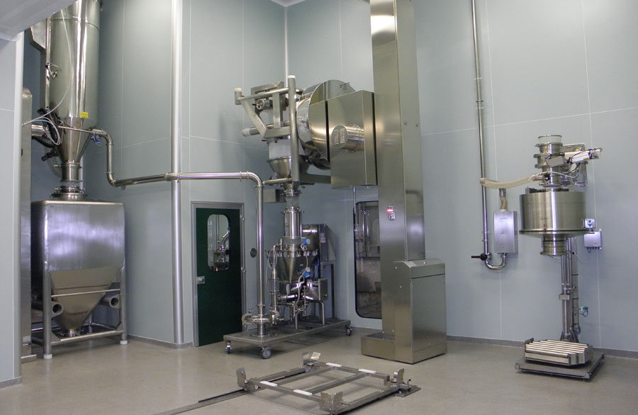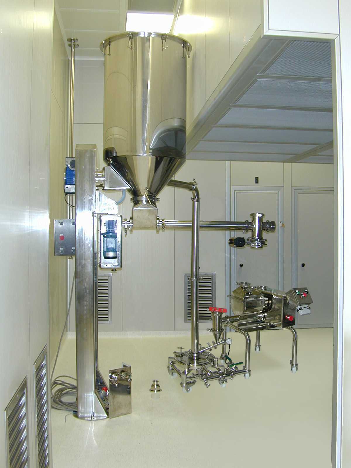
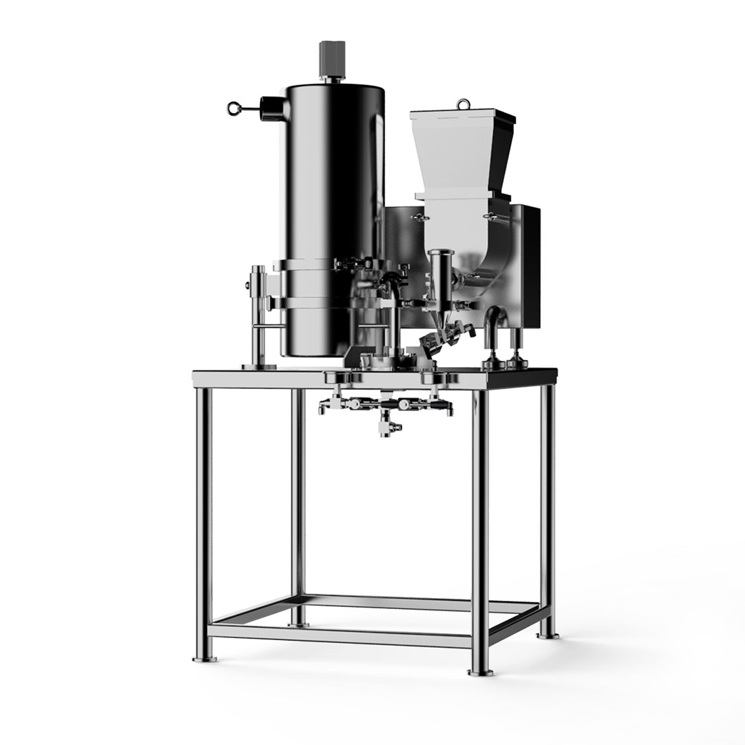
The prevailing technology for the micronization process is represented by spiral fluid jet mills.
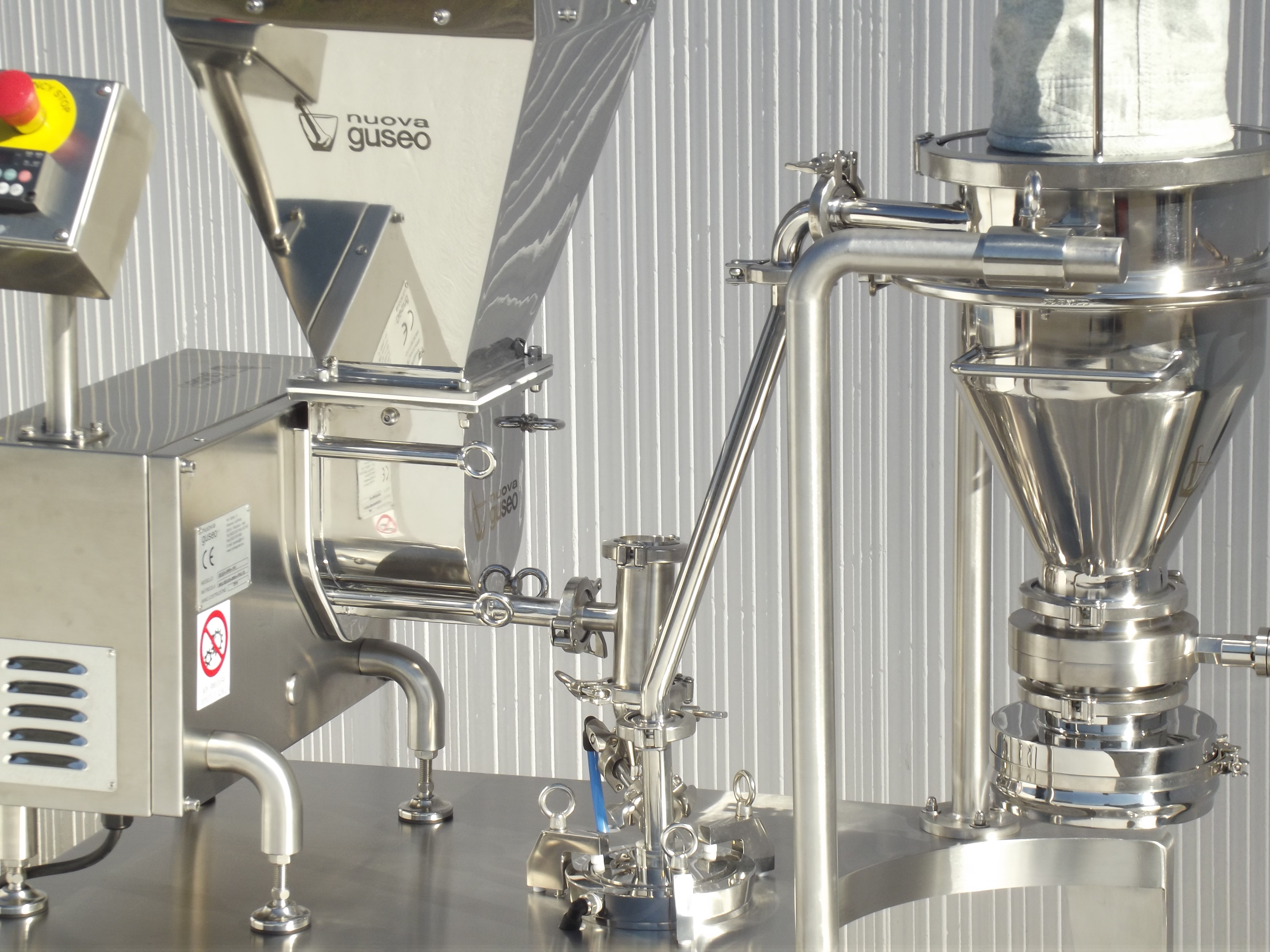
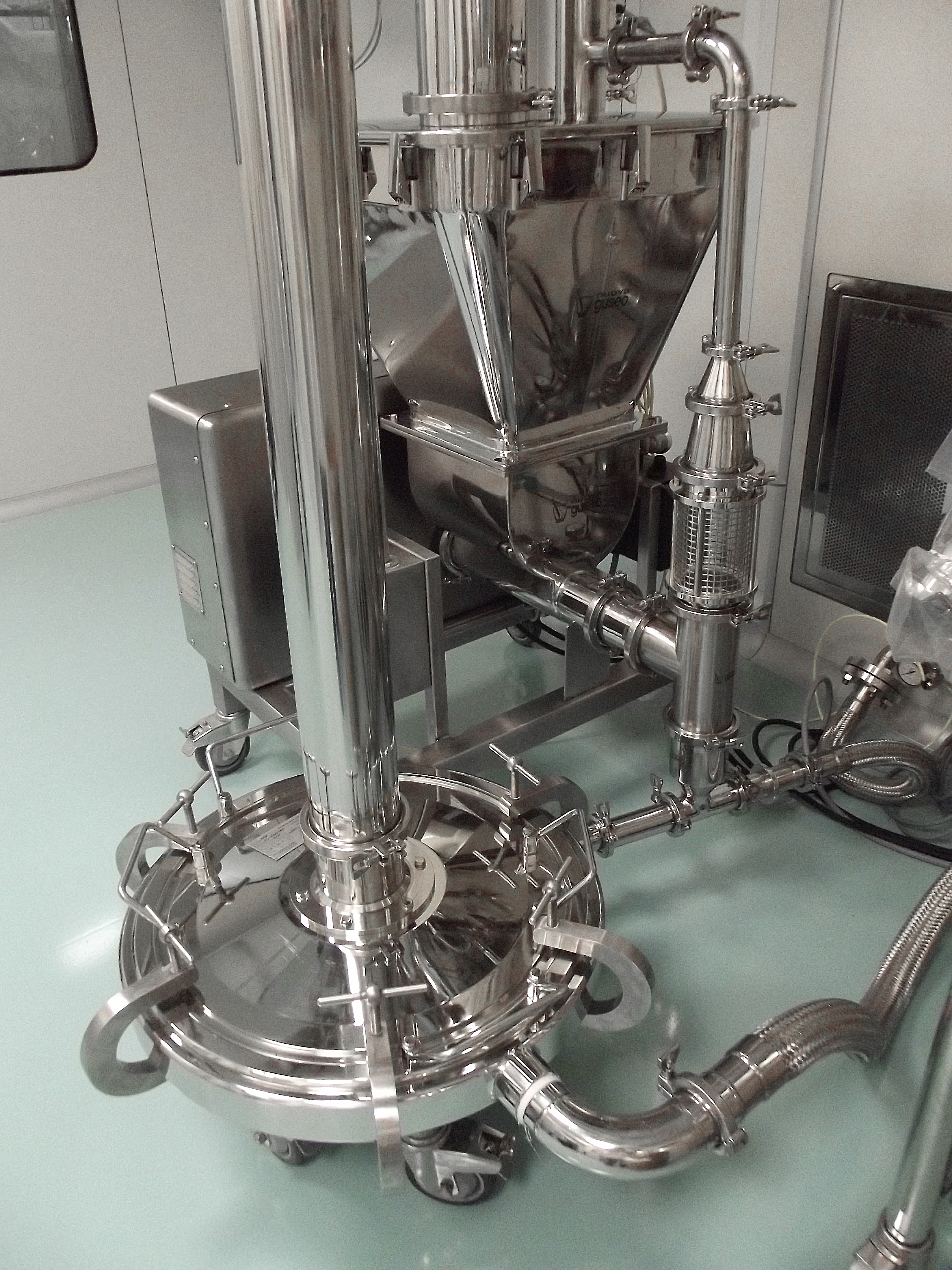
The operating principle does not include the use of grinding elements, since the reduction occurs exclusively by impact between the product particles, introduced into the micronization chamber, in a circular shape, through a Venturi injector. The particles are rapidly accelerated by a flow of gas (compressed air, nitrogen, argon or steam) injected through nozzles located at the periphery of the micronization chamber and are dragged in a vortical motion that causes them to collide repeatedly, progressively reducing their diameter and the mass as long as the energy accumulated by them falls to negligible values.
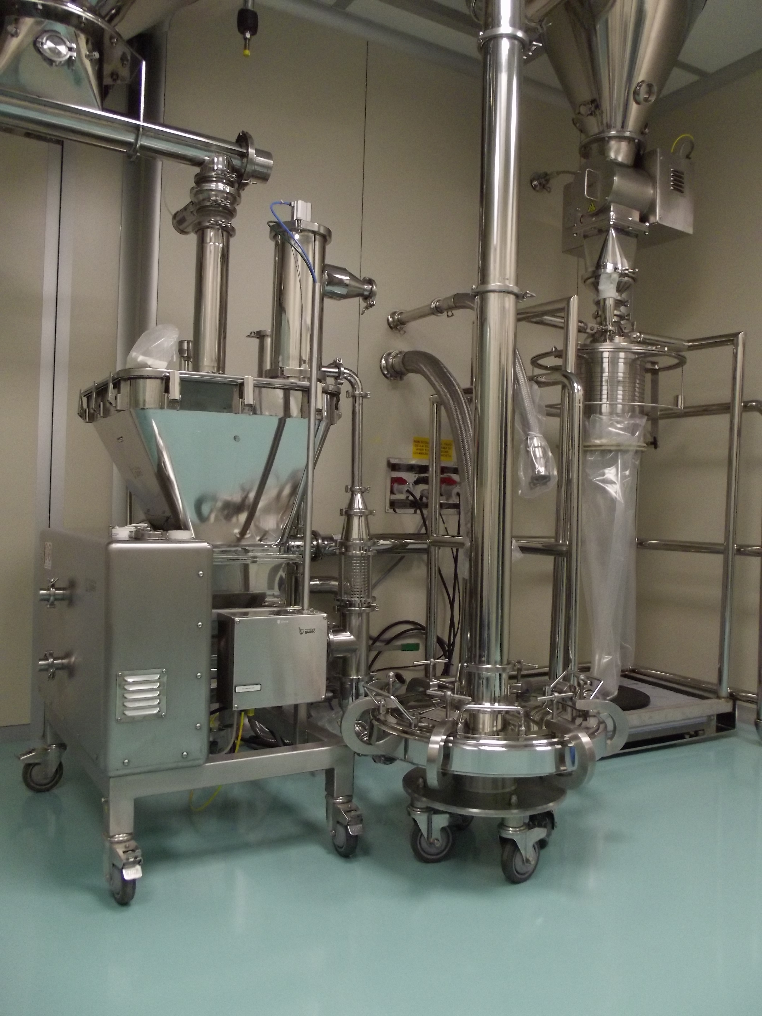
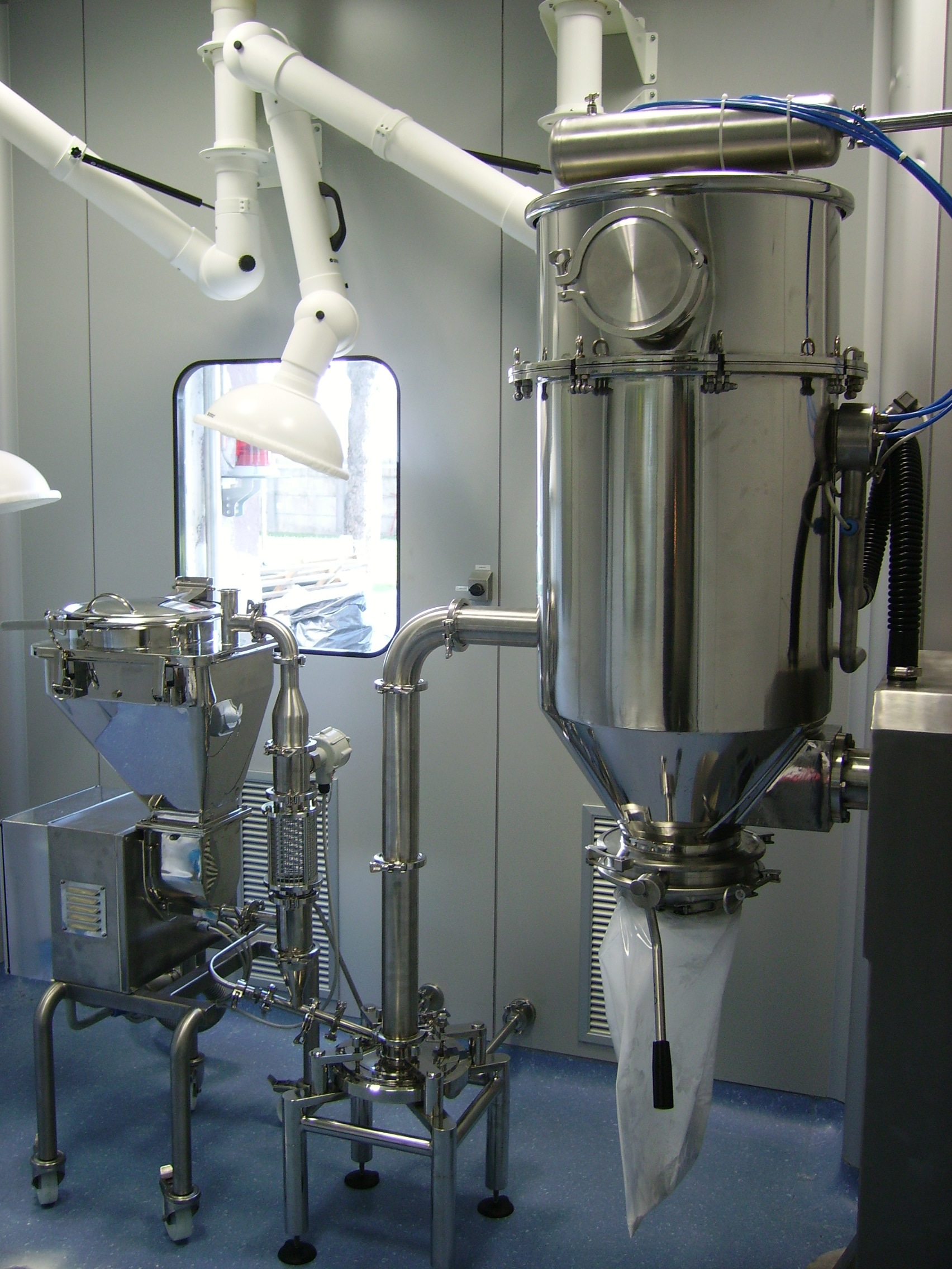
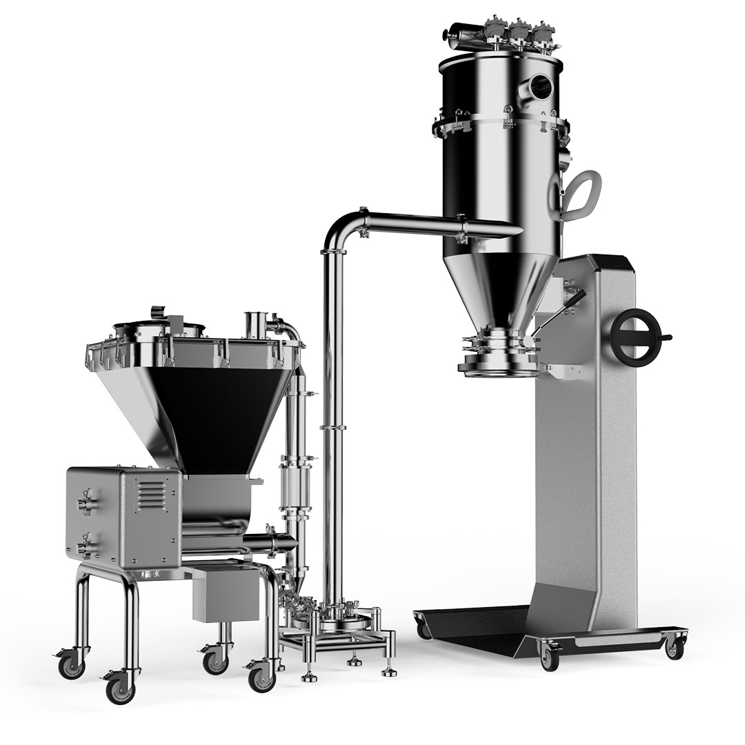
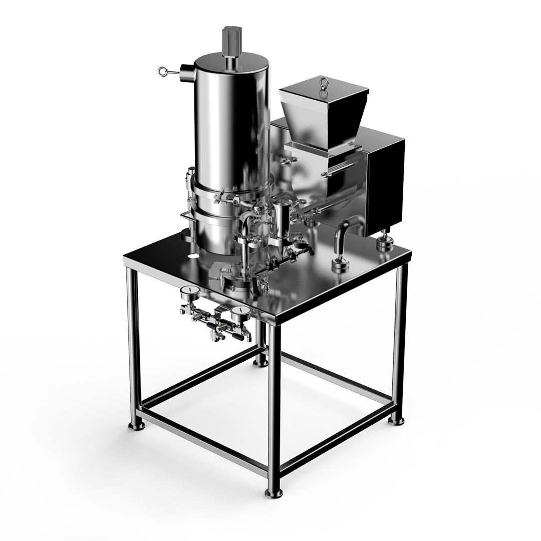
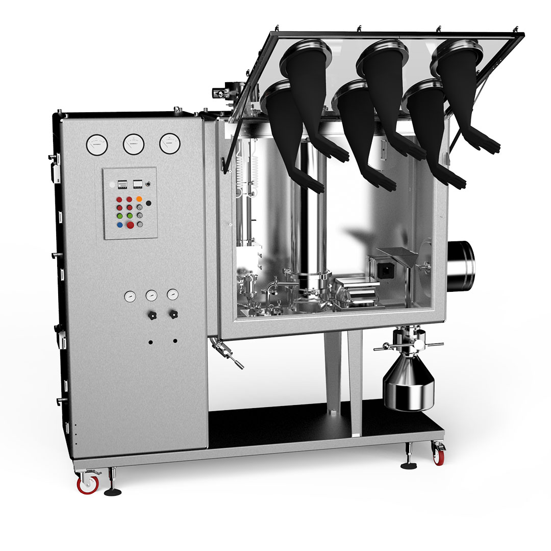
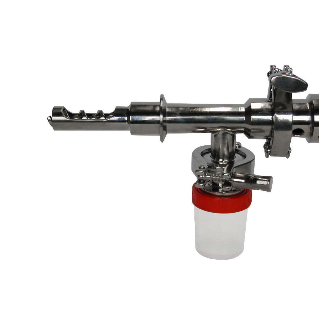
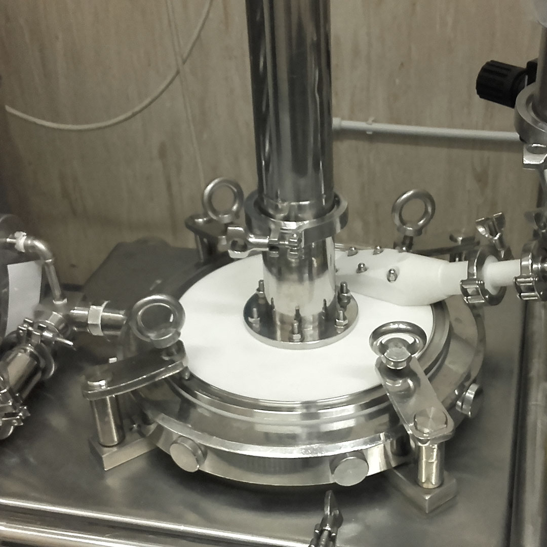
The micronized product particles are conveyed by the gaseous flow to a special separator cyclone filter, composed of a lower conical section, where the product is collected, and an upper cylindrical section, inside which a set of filter modules is housed, made of special fabric, which allows the exhaust of dusted air, while the finer micronized product is retained on the external surface of the same. The shaking of the filter modules takes place by means of a timed system with a counter-jet of compressed gas, which allows the removal of the micronized which is also collected in the lower conical part of the cyclone, allowing a high level of product recovery and optimal process efficiency of the system. For particular applications, such as integrated configurations in glove box isolator or, on specific request, octopus filter systems realized with inverted sleeves and pneumatic shaking.
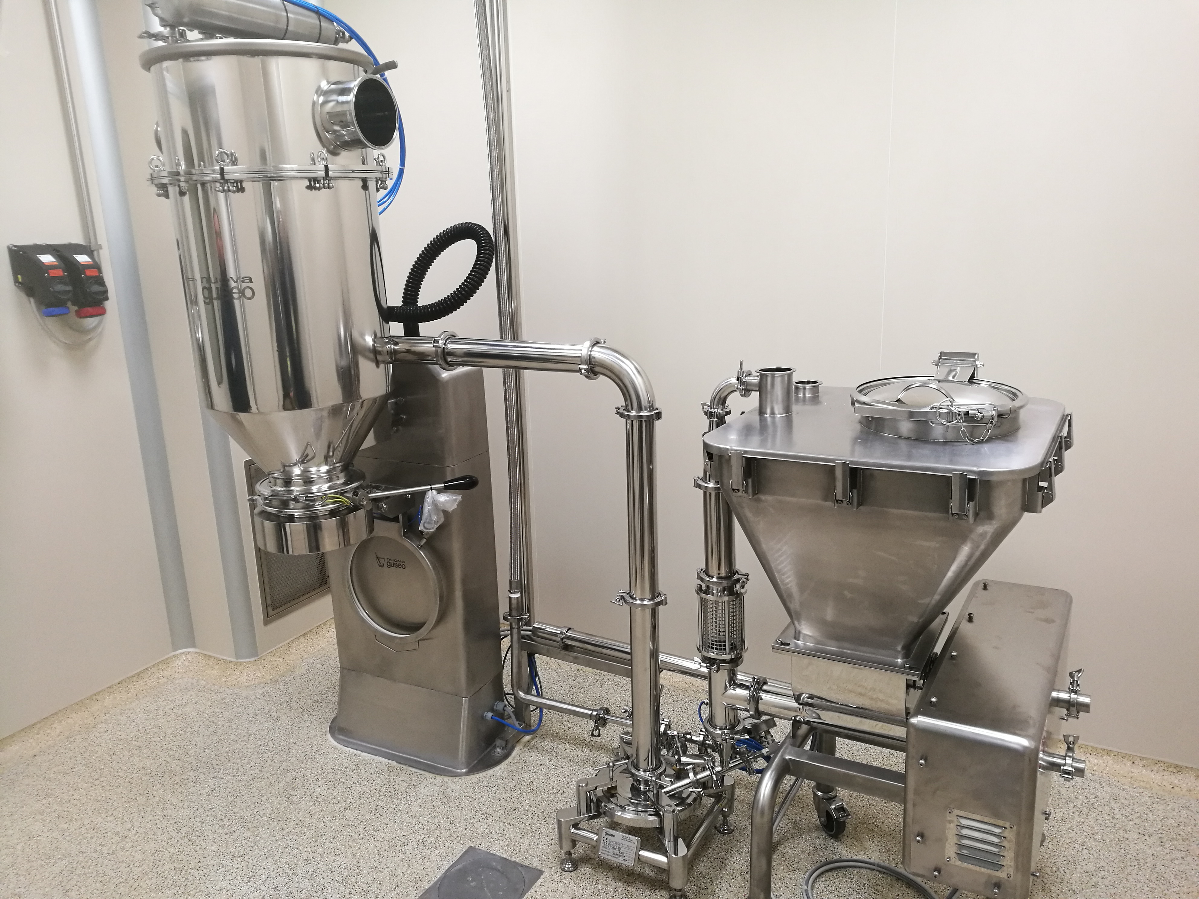
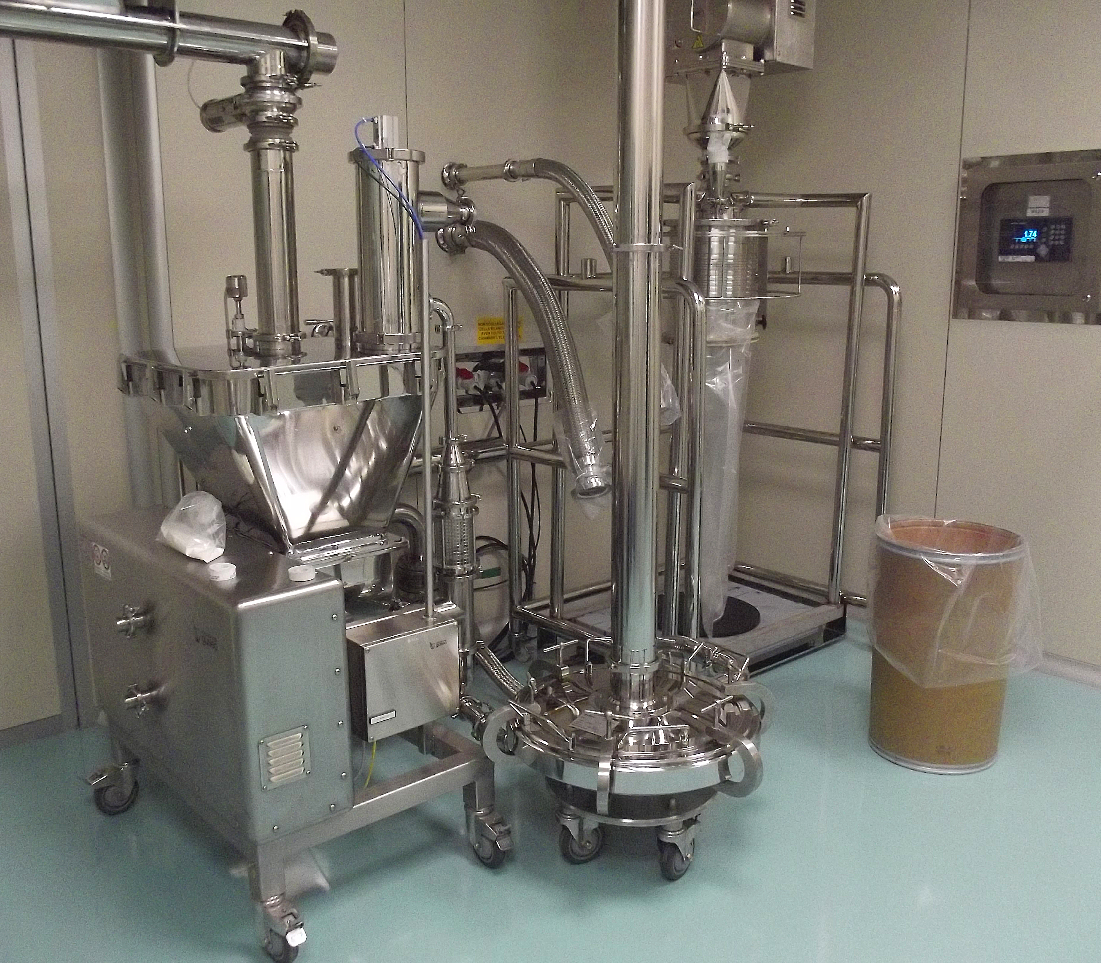
I mulini micronizzatori nuova guseo si sviluppano tramite una gamma di macchine che comprendono sia le versioni da laboratorio fino ai modelli industriali.
TECHNICAL DATA AND PRODUCTIVITY INDICES
The technical data and the productivity indices listed are purely indicative and may vary, even substantially, according to the product treated and the process requirements. for the aforementioned reasons it is always advisable to contact the company for more detailed information by submitting your projects / needs to our technicians so that we can advise and serve you in the best possible way.
| SCHEDA COMPARATIVA | M 100 | M 200 | M 300 | M 400 | M 500 | M 700 | M 900 |
|---|---|---|---|---|---|---|---|
| Diametro nominale: | 100mm | 200mm | 300mm | 300mm | 600mm | 750mm | 900mm |
| Capacità stimata: | da 0.05 a 5 kg/h | da 1 a 40 kg/h | da 5 a 80 kg/h | da 10 a 150 kg/h | da 100 a 500 kg/h | da 100 > 5000 kg/h | da 200 > 5000 kg/h |
| Lotto di lavorazione suggerito: | da 0.05 a 10 kg | da 1 a 100 kg | da 10 a 1000 kg | da 10 a 3000 kg | da 100 a 5000 kg | ||
| Finezza raggiungibile: | <5 µm * | <5 µm * | <5 µm * | <5 µm * | <5 µm * | <5 µm * | <5 µm * |
| Consumo gas di processo 1 7 barg: | 20 Nm3/h. | 100 Nm3/h. | 240 Nm3/h. | 600 Nm3/h. | 1400 Nm3/h. | 2300 Nm3/h. | 3400 Nm3/h. |
Grazie alla nostra lunga storia aziendale possiamo vantare numerosi casi di studio oltre a progetti custom realizzati interamente su misura per il cliente.